One of the main goals of this project was to make it an easy DIY build. The PCBs were designed to use common through hole components. If you're a beginner and are unsure about your ability to build this, read through these instructions to see if you understand them. If you have successfully completed a eurorack DIY build, this will be a breeze for you.
It is good idea to avoid low quality or knockoff brand components when sourcing your own. Most notably the ICs, and the trimmer. I have found that imitation Bournes trimmers do not hold their settings and drift dramatically. I highly recommend buying the real deal Bournes trimmers. With imitation ICs, you just never know what you are geting.
I've put together a mouser cart with the components needed to build the Klacking Keypad. If you are sourcing parts elsewhere, make sure the component dimensions are correct. Check the data sheets of the components on the mouser site if you are unsure.
Try and find capacitors that fit between the Power Board and the Control Board. There is about 11mm or 0.425" between the Power Board and the Control Board. Most capacitors will fit heightwise. Worst case scenerio, you can solder them on the other side of the Power Board.
For DIY builders who prefer a particular keyswitch, you may source your favorite keyswitches and install them on the Klacking Keypad Control Board as long as they fit the Control Board footprint.
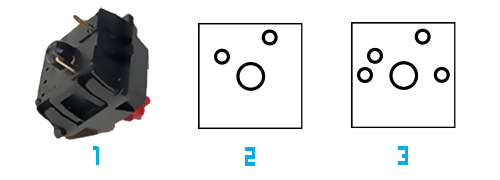
The Control Board footprints work with Cherry MX 3 pin frame mount keyswitches as well as 5 pin frame mount keyswitches. Number one above shows the bottom of a 3 pin Cherry MX keyswitch, which fits both number 2 and 3 footprints. This 3 pin keyswitch is what you want. You probably won't come across the 5 pin frame mount version but in case you have some of those on hand, the holes are there on the PCB board. Number 3 is the keyswitch footprint of the Klacking Keypad Control Board. The extra two holes on the 5 pin footprint are not needed for the keyswitch to function. Gaterons and other Cherry MX clones will work as long as they fit the footprints above. If you have the RGB version of the Cherry MX keyswitch, they have clear cases, those will work as well. If there is an LED installed, it will need to be removed or the the LED legs will need to be cut so the keyswitch fits the footprint.
You can purchase a keyswitch variety test kit on eBay and see which style you like best if you want to explore that rabbit hole. If not, I recommend either Cherry Silent Red, or Cherry Silent Black keyswitches. Pre-built modules will most likely have Cherry Silent Red keyswitches.
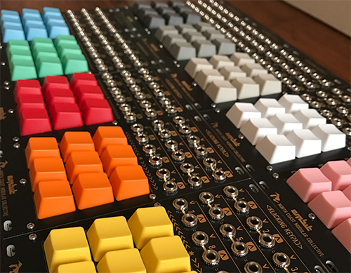
I purchased keycaps from WASD but they can be found elsewhere. The keycaps I use are Row 4, Size 1x1 Cherry MX keycaps. These come in a nice array of colors. You may also choose to use a mix of R4, R3 and R2 keycaps. Or R3, R2 and R1 keycaps. You can also purchase this set of number keys.
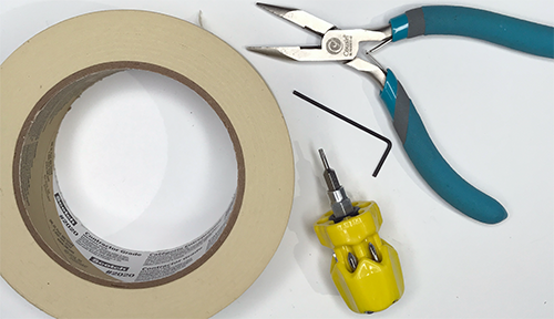
Beside your usual soldering setup, there are a couple of tools that may make the build easier. Painters tape, T6 Torx but driver, small pliers.
When we come to the part where we place the faceplate on the Control Board, some tape may help to keep things in place. Use a tape that is low tack, easy to cut into small pieces and easy to remove. Painters tape is perfect.
The M2 long bolts and nuts are small and a bit awkward. A 1.5M Allen wrench was provided with the PCB board kit but a T6 Torx bit will also fit. This Picquick 06102 Teeny Turner handheld driver comes with one. You will also need a small pair of pliers to hold the nut while you turn the bolt.
Take a moment to inspect the finished Power Board. Note the Orientation of the ICs, polarized caps, diodes, voltage regulator, trimmer pot and header sockets. These must be placed and soldered correctly for a functioning module.