The Klacking Keypad must be completely assembled before calibrating; the Power Board must be attached to the Control Board and expander port shunts in place. You will need a power ribbon cable that is long enough to hold the Klacking Keypad module in your hand while it is connected to your power supply.
We are going to set the internal voltage that is normalled to output 1. I'll assume that we want the normalled outputs to send a gate signal. In this example, we will set it to 8V. If you find that your modules aren't responding to the Klacking Keypad normalled outputs, it is likely that you will need to increase this internal voltage. It is possible to set the voltage anywhere between 0 and 10 volts, so if you need a specific positive voltage, you can adjust it through this method to fit your needs.
While performing this procedure, do not touch the PCB board with anything while powered up.
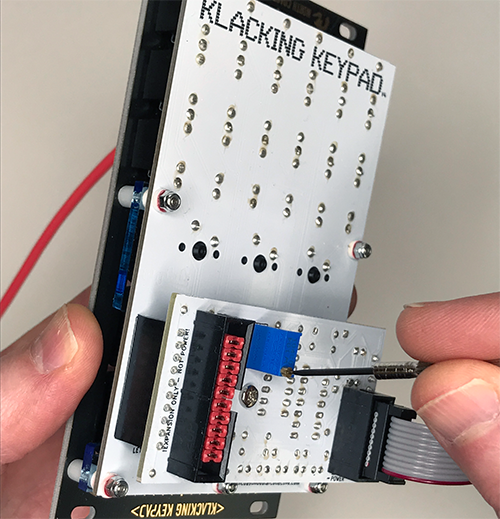
Get a long power ribbon cable. Plug the Klacking Keypad into your eurack power supply. Plug in a patch cable into output 1. Plug the other end of the cable into a tool that will display voltages. Power it up. Pick up the Klacking Keypad with your hand on the face side of the module. With the hand that is holding the module, hold down output 1's keyswitch with your finger. You should see a positive voltage on your readout.

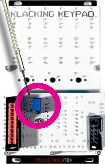
Turn over the module so you can see the blue trimmer. With the other hand, adjust the voltage by turning the trimmer's wiper with a small flat head screw driver. Clockwise will increase voltage, counter-clockwise will decrease voltage. When you see your desired voltage, 8V, your all set.
No problem. It is not vital to have the internal voltage set perfectly. We just need a voltage setting high enough to trigger our modules. Perform the procedure above, but instead of plugging the output cable into a voltage measuring tool, plug it into a module that accepts gate signals. If your module does not react to the signal from output one, increase the voltage by turning the trimmer clockwise until you get a reaction. Give the trimmer one more turn for good measure.