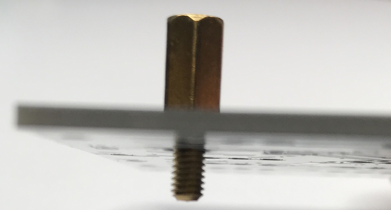
1. Place the spacer with the male/female ends at the top of the PCB with the male end facing down.
2. Screw a female spacer to the bottom of the male/female spacer.
3. Place a spacer at the bottom of the PCB. Bolt on top, female spacer on the bottom.
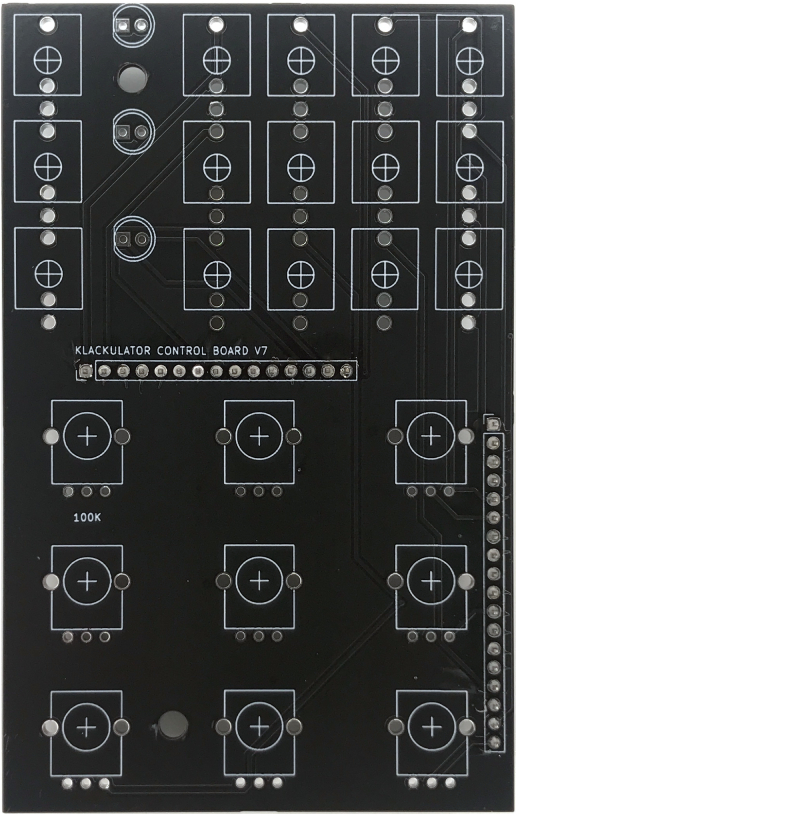
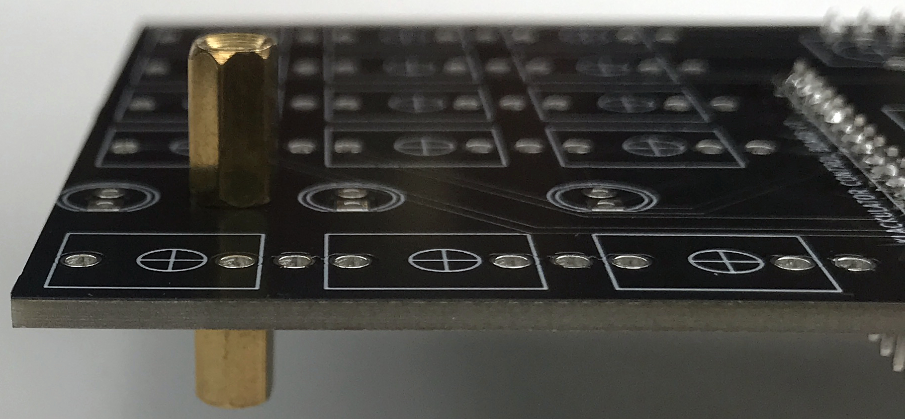
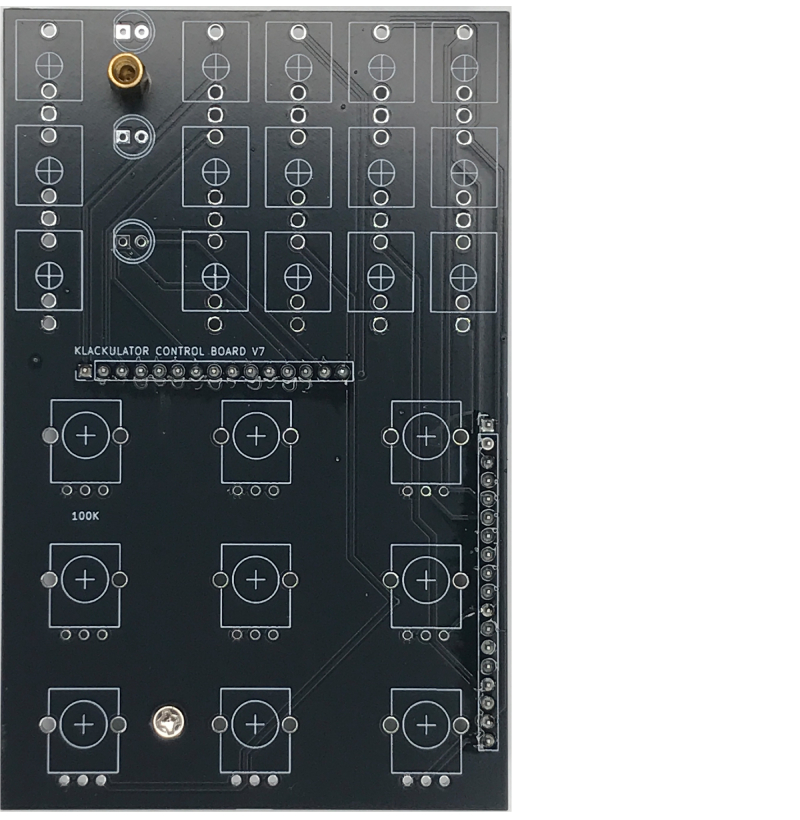
4. Your control board should now look like this.
5. Place all your components but do not solder anything.
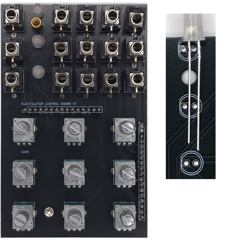
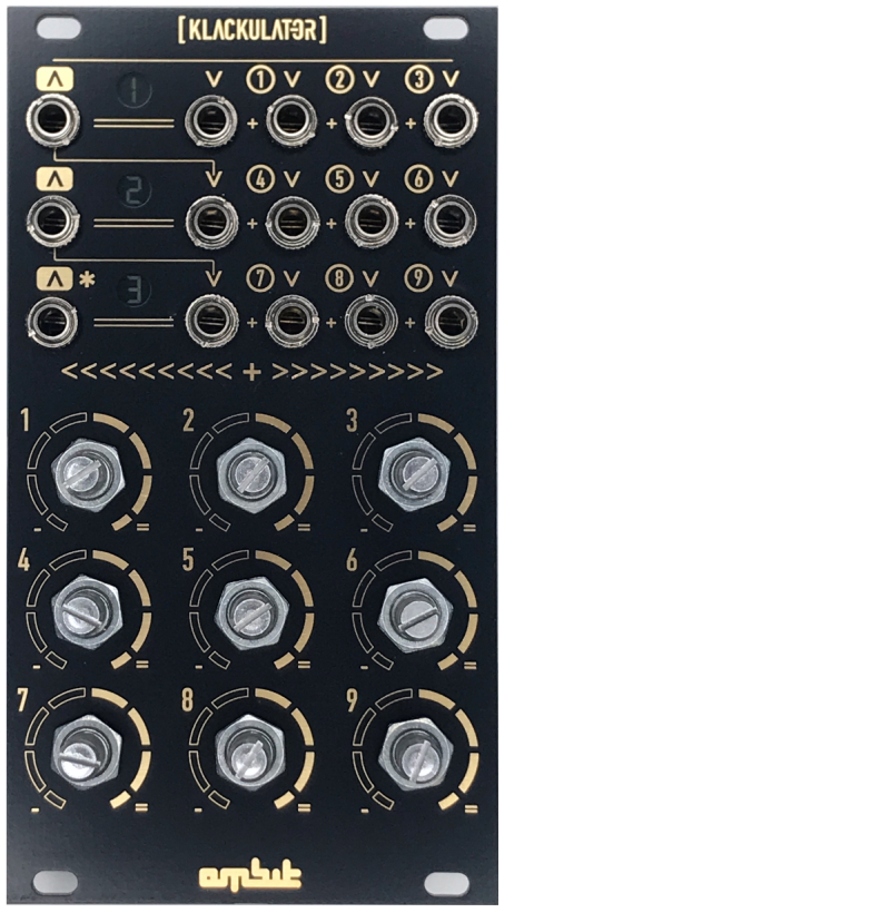
LEDs must be Bi-Color meaning that they can handle both positive and negative voltage. LEDs should be placed with the flat edge mathing the PCB board graphic, long pin goes through the right hole of the board.
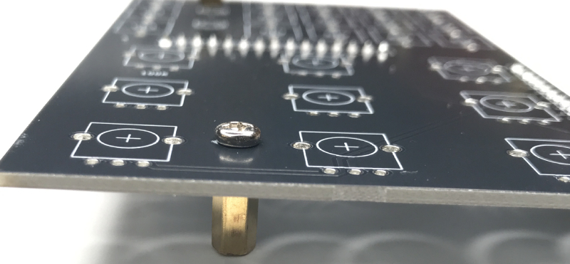
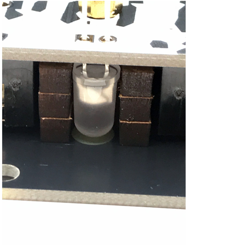
6. Place the LED spacers as shown. There are three that stack.
7. Place the faceplate on top with pots and jacks through the faceplate holes. Place and hand tighten all pot and jack nuts.
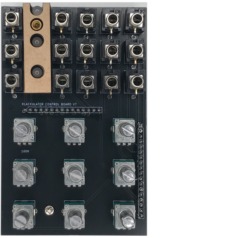
8. The LEDs should be able to touch the faceplate. Try moving them up and down to see if you can hear them tap the PCB. Once everything is lined up, solder all components.
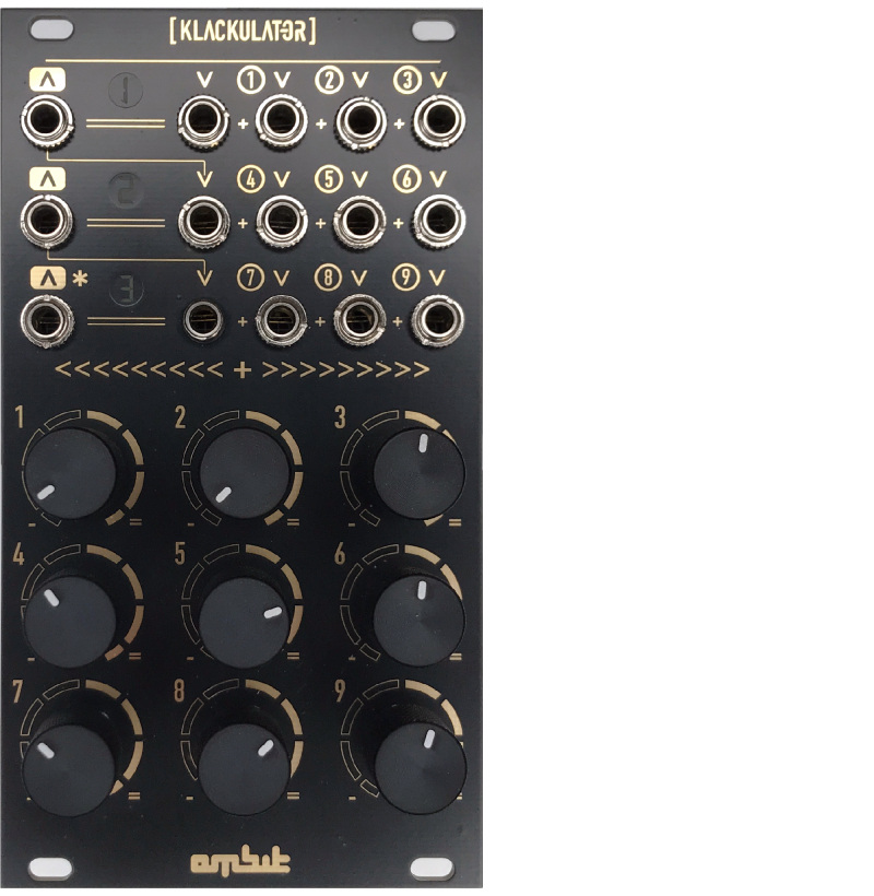
8. Make sure everything has been soldered. Before putting on your knobs, power it up to see if everything works. Add knobs when everything checks out.