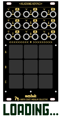

One of the main goals of this project was to make it an easy DIY build. The PCBs were designed to use common through hole components. If you're a beginner and are unsure about your ability to build this, read through these instructions to see if you understand them. If you have successfully completed a eurorack DIY build, this will be a breeze for you.
It is best to use quality components from reliable sources. Avoid buying the cheapest knockoff op-amps on eBay. If they don't work, it will waste everyone's time. For modules that control voltage such as this one, 1% tolerance resistors are a must.
For the male and female pin headers, buy a few long pieces and cut them down with your wire cutters. The number of pins on each header are not standard, so you might have a hard time finding them premade.
The LEDs must be Bi-Color. I plan on supplying them with the PCB boards but if you want to use a different color, make sure they are Bi-Color to handle both positive and negative voltage.
Standard soldering set up, an alan wrench for the knobs, and a screwdriver for your spacers. That's really all you need for this one.
If your a beginner, make sure to follow the instructions in order. There aren't a lot of gotchas in this build but there are a few details that if ignored, will render the module useless. Standard things like component polarity, soldering components too early etc. Take your time and good luck!