We will build the Power Board before building the Control Board.
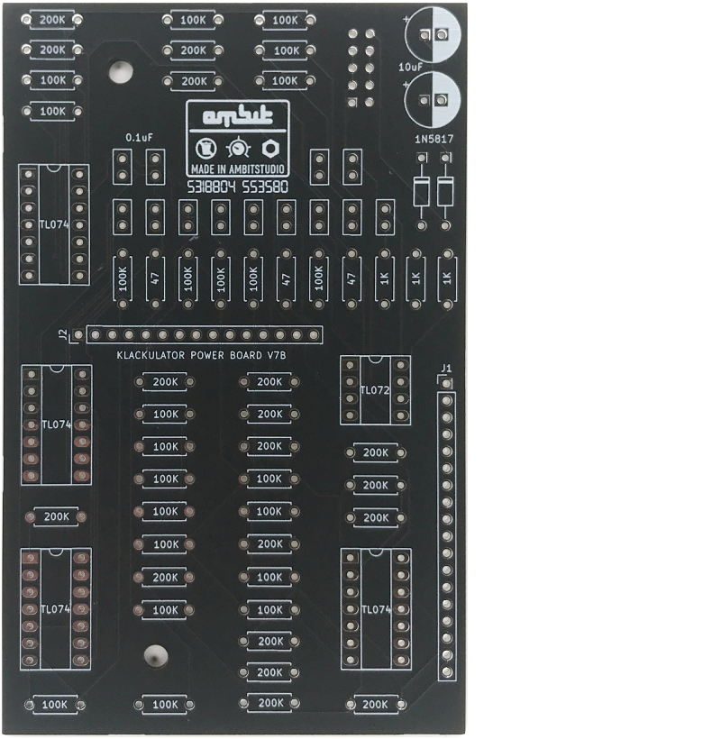
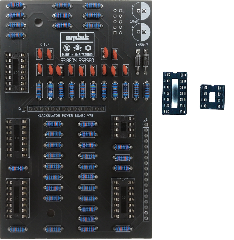
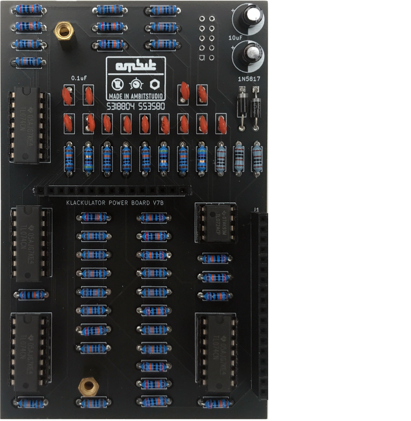
Grab Your Power Board and Components.
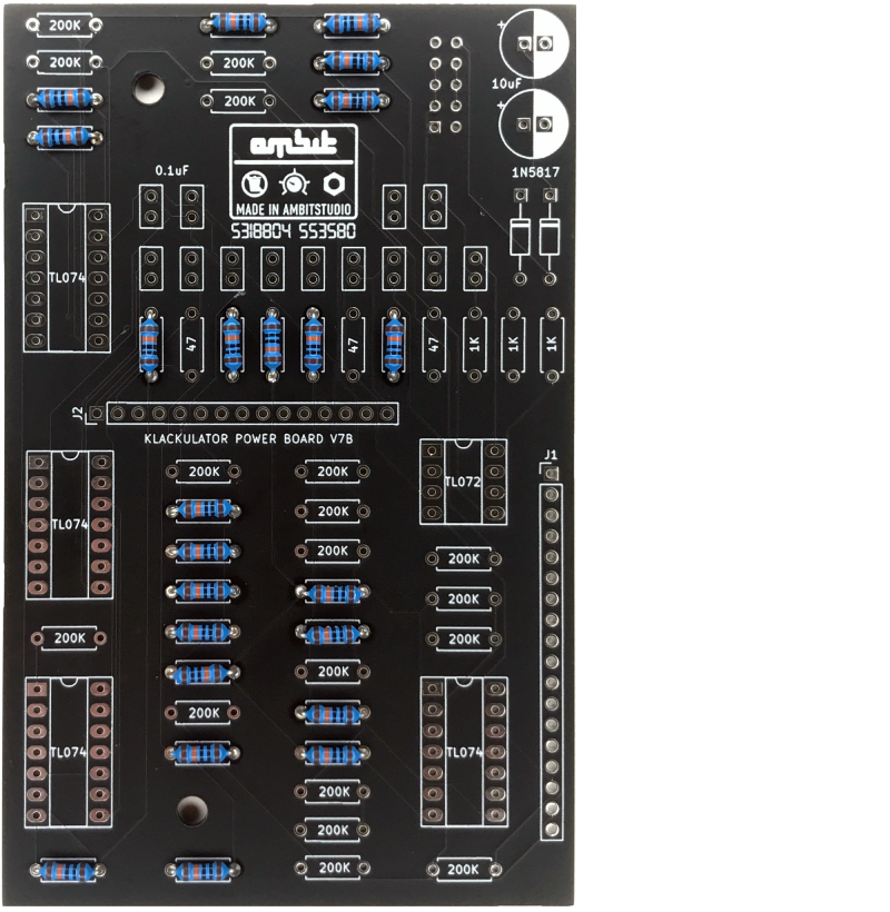
1. Place and solder the 100K resistors.
2. Place and solder the 200K resistors.
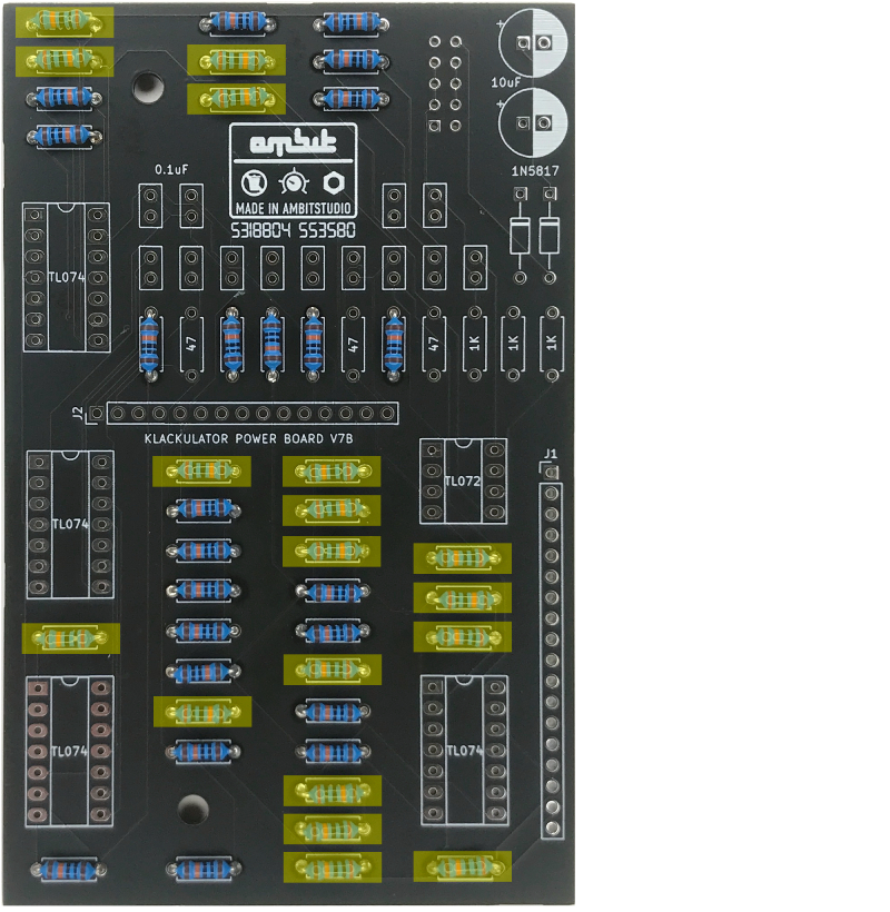
3. Place and solder the 1K resistors.
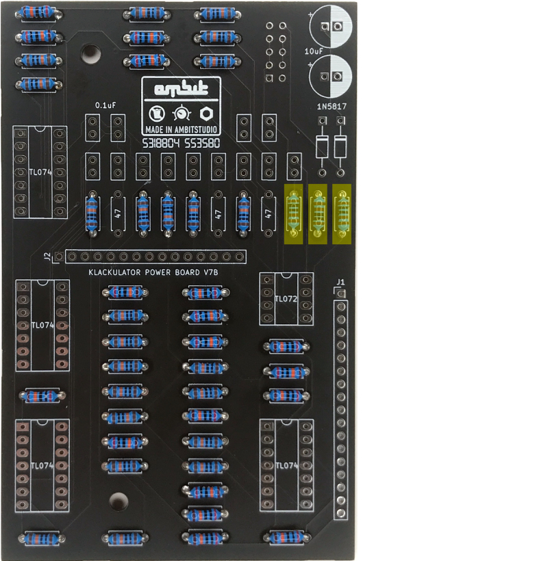
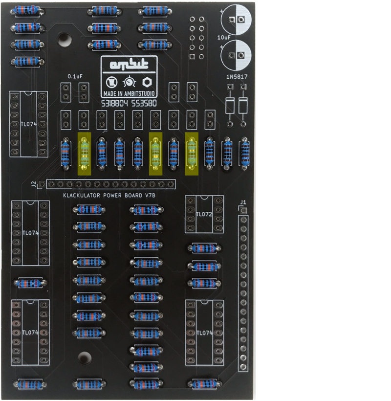
4. Place and solder the 47 ohm resistors.
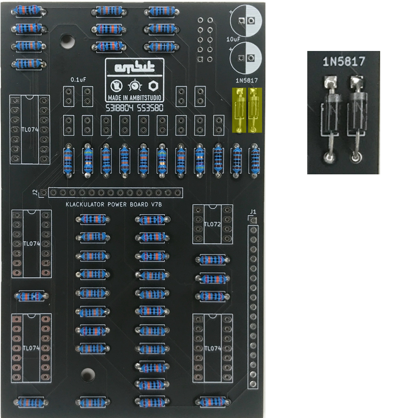
5. Place and solder the 2 1N5817 diodes.
Make sure the stripes on the diodes match the stripes on the board.
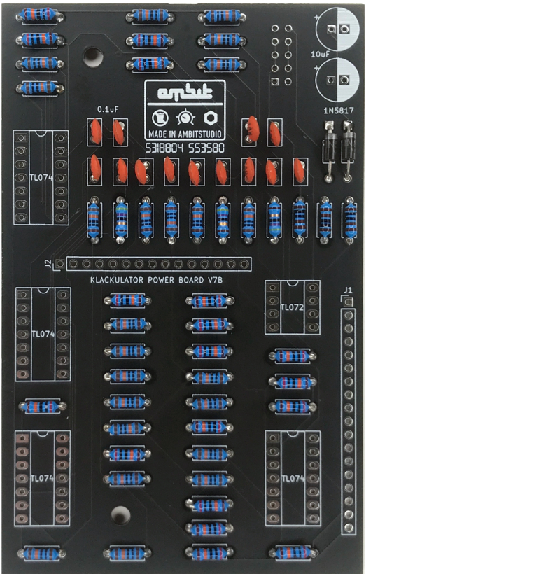
6. Place and solder the 0.1uf capacitors.
7. Place and solder the IC sockets.
Make sure the notch in the socket is pointed up.
You could just solder the ICs directly to the board and not use sockets but sockets are recommended in case an IC fails and needs to be replaced.
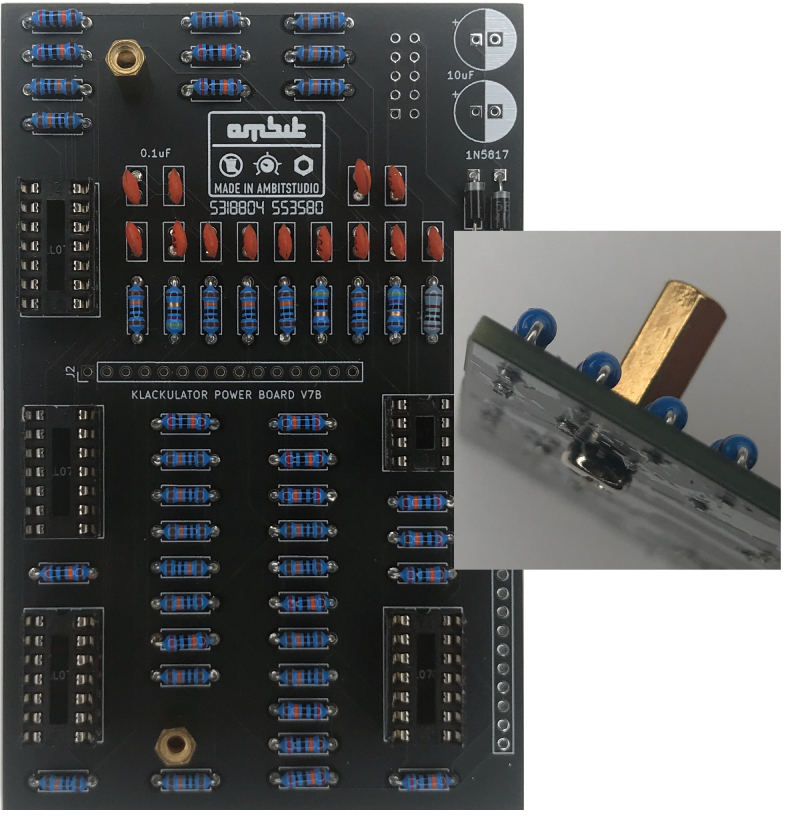
8. Place 2 spacers as shown, bolts on bottom.
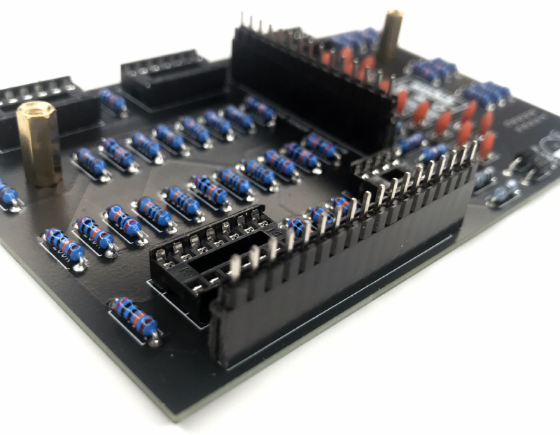
9. Place 2 pin connectors, female side on bottom.
DO NOT SOLDER YET.
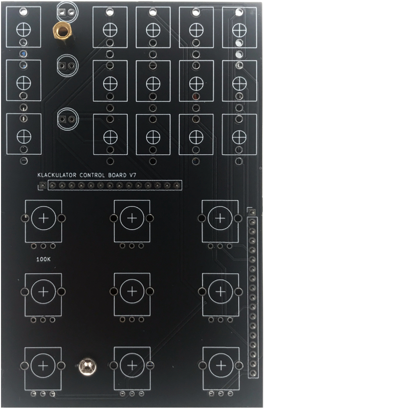
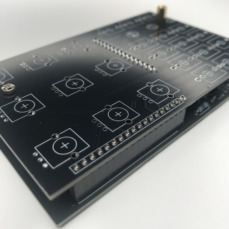
10. Place control board on top of power board. Screw in bolt on bottom spacer, screw in male/female spacer on top spacer. Solder pin connector pins on both sides.
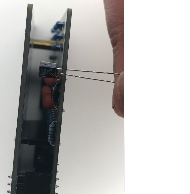
11. While you have the two panels attached, check to see if the two 10uF capacitors will fit when soldered to the top of the power board, between the power and control boards. If not, the capacitors can be soldered to the bottom of the power board.
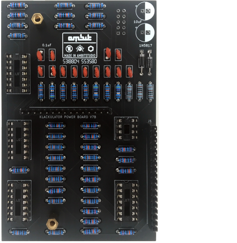
12. Detach the two boards. Place and solder the two 10uF capacitors.
Make sure the negative side of the capacitors (usually marked with a white or black stripe with a minus sign) match the white side of the PCB board symbol.
13. Place your IC chips, notches up. If no notch is present, their should be a circle which should be at the top. See chips in image above.
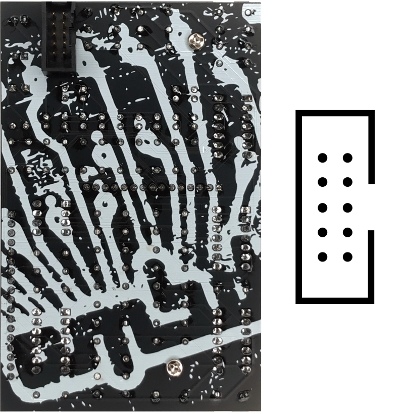
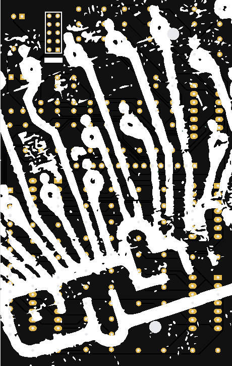
14. Finally, place and solder your power pin connectors or shrouded header.
If using a shrouded header, the side with the opening should face right.